

software for thermal bridges, mould and condensation

software for windows and curtain walls
You used to have to learn. Now you just ask.
Calculate thermal bridges and windows with an AI assistant that shows you how it is done, checks what you are doing and explains every step. The calculation sequence is the same as ever, but you no longer face it alone.

Ask as you would ask an expert colleague
Try these prompts
- Goal: what you need (Ψ, fRsi, mould and condensation check), for which use and with which dimension reference (internal or external).
- Geometry: from your own DXF, or from a parametric Bridge Generator template. For your case there are two groups of templates: wall with floor over an unheated room below (e.g. cellar, garage) and wall with ceiling towards an unheated room above (e.g. attic), with or without ring beam, ring beam correction, balcony, and with external, internal, cavity or no insulation.
- Layers and dimensions: wall and floor layers, ring beam, cut-off lengths of the model.
- Materials: assignment and check of the conductivities.
Read the full answerClose
- Boundary conditions: heated interior, exterior, unheated room, adiabatic sides, location and humidity class.
- Model check and simulation.
- Results: L2D, Ψ, fRsi, minimum surface temperature, mould and condensation views.
- Report as a PDF.
In the Elements tab there is no closed path: instead there are three section elements (wall, frame, panel).
Without that segment the program does not know which sides to make adiabatic when it simulates the window on its own.
In the simulation settings mould and surface condensation are disabled: only the flows simulation was run, so there is no ISO 13788 verdict.
Read the full answerClose
This way the program calculates:
Ψ = L2D − Σ U·l = 1.014 − 0.929 = 0.085 W/(m·K)
- The section elements on frame and panel must be removed, leaving only the wall one, which already correctly reaches the frame.
- The closed path must be drawn around the window (frame + panel), excluding the subframe.
The segment goes on the side of the wood-cement subframe in contact with the frame (x ≈ 2.668).
The internal face of the two frame blocks has the “Internal” boundary (analysis group “wall”) instead of “Window Internal”, which is now only on the panel. With the checks re-enabled, the frame would be assessed for mould like the masonry, instead of for condensation only.
- Location: the climate zone is set to a town in the province of Novara, at 162 m. Please confirm it is the one of the building site.
- Frame: it is a solid block called “Aluminium” with λ = 0.12 W/(m·K). If it is an equivalent conductivity that is fine, but it is better to rename it.
- Wall length: it is modelled for 1.0 m from the reveal. With a thickness of 53.5 cm, ISO 10211 would require 3 times the thickness, i.e. about 1.6 m. The effect here should be small.
- Project and geometry.
- You start from a template of the “FS – Windows” series: “Window – h node” for horizontal sections, like yours, which is a side section; “Window – v node” for bottom and top sections.
- There are two series, which differ in how air cavities are treated: series 1 with the radiosity method; series 2 with the equivalent conductivity.
- Then you import the DXF with a scale factor of 0.001, because it is in mm.
Read the full answerClose
- Materials.
- The frame is filled with the real materials: aluminium, polyamide strips, insulating inserts, EPDM gaskets.
- The glazing must be replaced with the special “10077-2 Insulation” material (insulation panel, λ = 0.035 W/(m·K)).
- The air chambers remain cavities: the program calculates them according to the standard.
- The rectangle on the wall side becomes adiabatic.
- Boundary conditions.
- Interior and exterior with the surface resistances of the standard.
- Adiabatic towards the wall and on the panel cut.
- The template already sets most of them.
- Check and simulation. The program calculates the conductance L2D and derives Uf with the formula of the standard:
Uf = (Lf2D − Up·bp) / bf
- generates the section elements by itself, i.e. the frame width bf and the panel width bp;
- bf however must always be checked: it is measured up to the end of the frame as seen from both sides, without the gaskets.
I need a working folder on the PC, where to save the DXF, the project, the images and the report.
| Measure | fRsi sim. | Mould |
|---|---|---|
| Current state | 0.495 | 1612 mm |
| External insulation on the lower wall, 3.5 cm of rock wool | 0.666 | 86 mm (corner) |
| 5 cm external insulation | 0.680 | 15 mm |
| 6 cm external insulation | 0.686 | 0 ✓ (minimal margin) |
Read the full answerClose
| Measure | fRsi sim. | Mould |
|---|---|---|
| 7 cm external insulation, as on the floor above | 0.690 | 0 ✓ |
| 10 cm external insulation | 0.699 | 0 ✓ |
| Lower wall in 30 cm clay block instead of concrete | 0.631 | 94 mm |
| Internal insulation on the wall only, 1.5 or 4 cm | 0.514 / 0.486 | ~140 mm (the corner with the ceiling gets worse) |
| Internal insulation, 4 cm on the wall + 3 cm on the whole ceiling | 0.753 | 0 ✓ |
- Continuous external insulation on the lower wall (geometry): it is the most natural solution. A resistance of at least about 1.6 m²K/W is needed: 6–7 cm of rock wool, or about 4 cm of an insulation with λ ≈ 0.022 (PIR or phenolic). Beyond 7 cm the result improves little, because at that point the balcony slab governs.
- Insulation of the soffit and of the edge of the balcony, connected to the external insulation (geometry): it reduces the thermal bridge of the slab and gives margin to the external insulation, which with 7 cm stays just above the limit.
- Thermal break of the balcony (load-bearing insulating element between the balcony and the floor): it is the most effective measure on the corner, but it changes the structural design.
- Internal insulation of the lower wall: it only works with a return on the ceiling. Without the return the corner gets worse. With the whole ceiling insulated the check is passed with a wide margin; a return of limited length (50–60 cm) must be verified by drawing it. In this case the Glaser check behind the insulation is also needed.
- Materials only, without insulation: rebuilding the wall in clay block is not enough.
- I did not draw the thicknesses. I simulated them by giving the existing layers an equivalent λ with the same resistance: for the external insulation the 3.5 cm external render layer, for the internal insulation the internal plasters. With the geometry drawn the values will change only slightly.
- In these variants warning W0025 appeared: a temperature below the external one in the external corner under the balcony. It is local, it comes from the equivalent λ and does not affect the internal surface. In fact the results are the same with high and very high quality.
- I enabled the mould check in the simulation settings: before there were only the flow results.
- I restored the original materials. In the materials list concrete, external render and internal plaster now appear twice, with identical properties.
- I did not save the file.
2D or 3D, steady-state only or transient too
Let the program do the work for you
Two ways: ask an AI assistant in plain words, or write a script that repeats the calculation as many times as you like.

The program connected to your AI assistant
Mold Simulator and Frame Simulator 9 include an MCP server, called Heatsim, which makes the program commands available to Claude, ChatGPT, Cursor, VS Code or Codex. The assistant reads the open project and works in the program: it imports the DXF, assigns materials and boundaries, simulates, reads the results and lays out the report.
- It starts with the Heatsim button in the view bar.
- It is included: it works with an active Updates & Upgrades subscription.
- The AI assistant (Claude, ChatGPT or other) is your own service.

Automatic calculations with scripts
The Scripting Module is a plugin to automate Mold Simulator and Frame Simulator with Python scripts: series of variants, repetitive calculations, reports. Write the procedure once and repeat it on all the cases you need.
- It is a separate plugin, for those who want to program their own procedures.
- It is not needed for the connection with the AI assistant.
- Documentation available in five languages.
From drawing to simulation in fewer steps
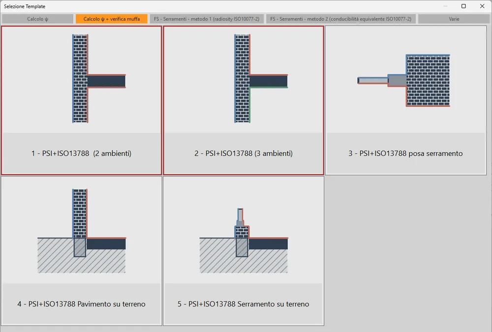 Mold Simulator
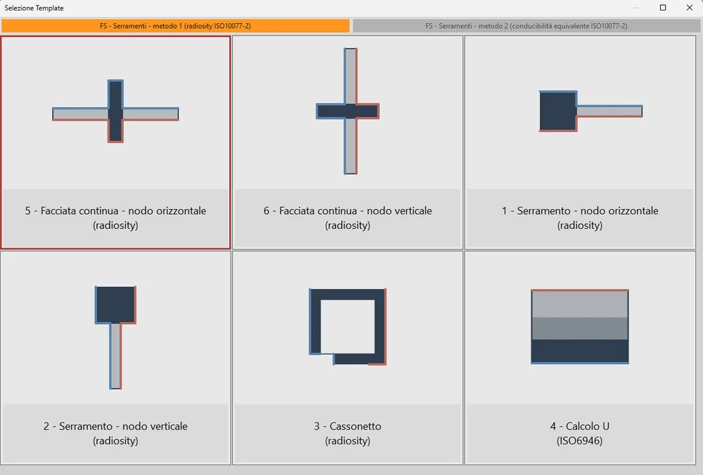 Frame Simulator
Template suggested from the DXF
When the DXF is loaded, the program identifies the suitable templates and highlights them for you: you choose which one to use.
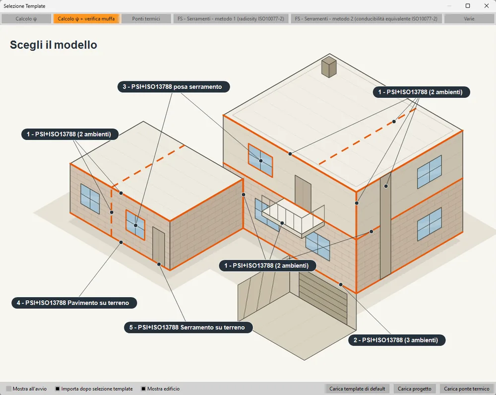 Mold Simulator
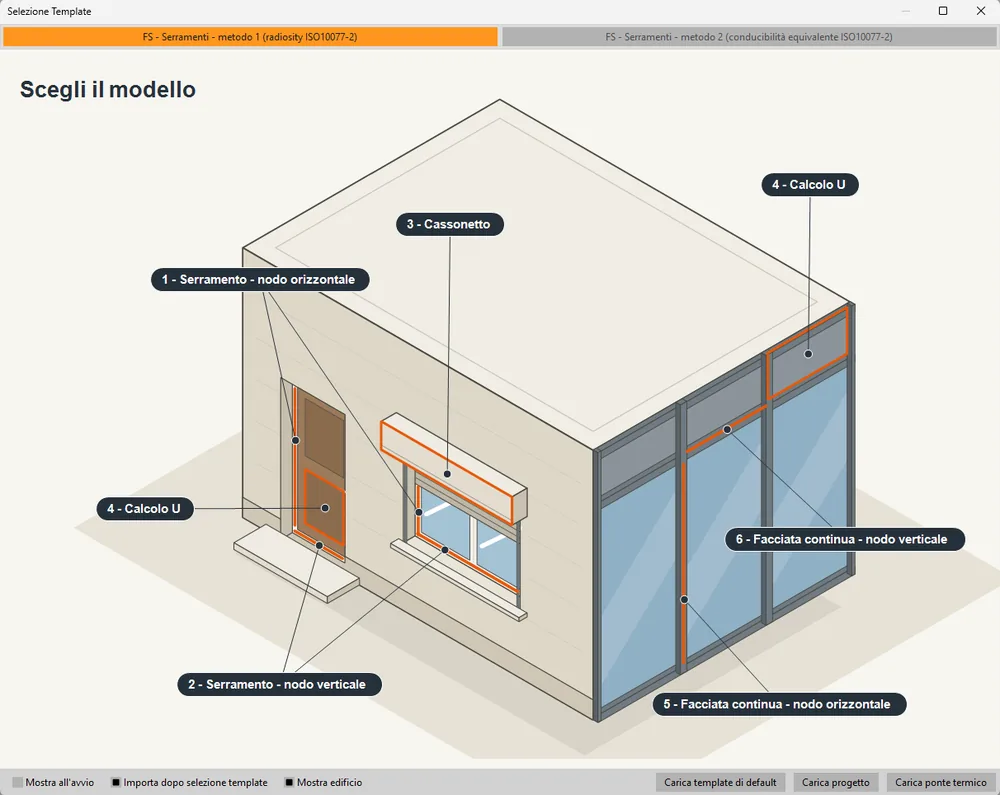 Frame Simulator
Template chosen from the building
If you prefer to choose yourself, click the point of the building you are interested in: thermal bridges, window laying and ground floor in Mold; window, roller shutter box and curtain wall in Frame.
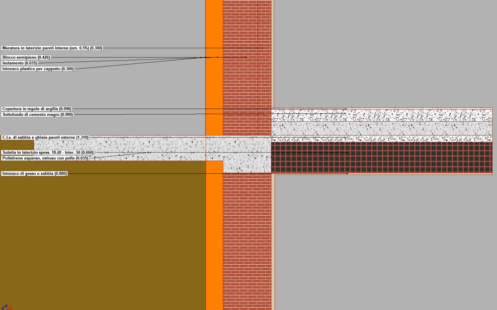 Mold Simulator
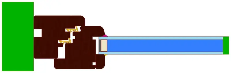 Frame Simulator
Automatic material assignment
A model trained on real sections suggests the material of each area. You confirm the uncertain cases in a table.
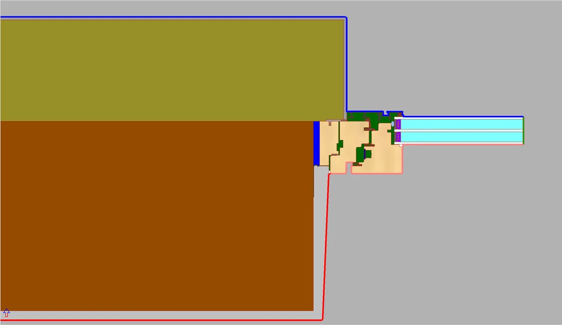 Mold SimulatorFrame Simulator
Boundaries with one click
Interior, exterior, ground, unheated room and window laying assigned by the program.
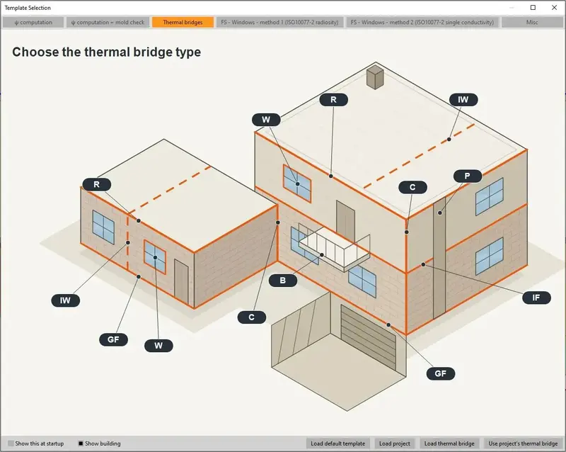 Mold Simulator
624 ready-made thermal bridges
Choose the junction by clicking on the building. New pitched roof junctions, underground garage and all the UNI 11979 window installation junctions.
Watch version 9 at work


Much faster simulations
The biggest gain is in 3D, with more stable calculations too.
Five languages
Program, libraries and manuals in English, Italian, French, German and Spanish.
Reports straight to PDF
Unlimited project tags and header images saved in the file.
Material labels
Name and conductivity of each area, readable even in layers a few millimetres thick.
How to move to version 9
With an active Updates & Upgrades subscription version 9 is already included, and with it the AI connection. Do you have version 8 or earlier? You will find all the options on the Software Updates page.
